Building: case studies

Airflow optimization in a cleanroom

OptiFluides runs CFD simulations of the aeraulics in cleanrooms, in order to validate the layout of diffusers and air intakes and, if necessary, make recommendations for improvements.

Context

Cleanrooms are used in many sectors, including the pharmaceutical, food and automotive industries.

Cleanroom design involves strict control and maintenance of temperature, humidity and particle levels. Numerous constraints make this design difficult:

  • speeds may be locally limited when handling volatile products,
  • equipment emitting high levels of heat may be present,
  • the humidity of the various blowers may differ…

It may also be necessary to maintain certain equipment or rooms at over-pressure, to prevent contaminants from entering, or at under-pressure, to prevent potentially dangerous particles from escaping.

The challenge of cleanroom design therefore lies in controlling all the aeraulic phenomena at work, at different scales and in different zones of the room under study.

Objective

The main challenge is to guarantee a minimum particle concentration inside these cleanrooms. The regulatory concentration threshold, expressed in particles per cubic meter, varies for each particle diameter and depends on the cleanroom classification (from ISO 1 to ISO 9).

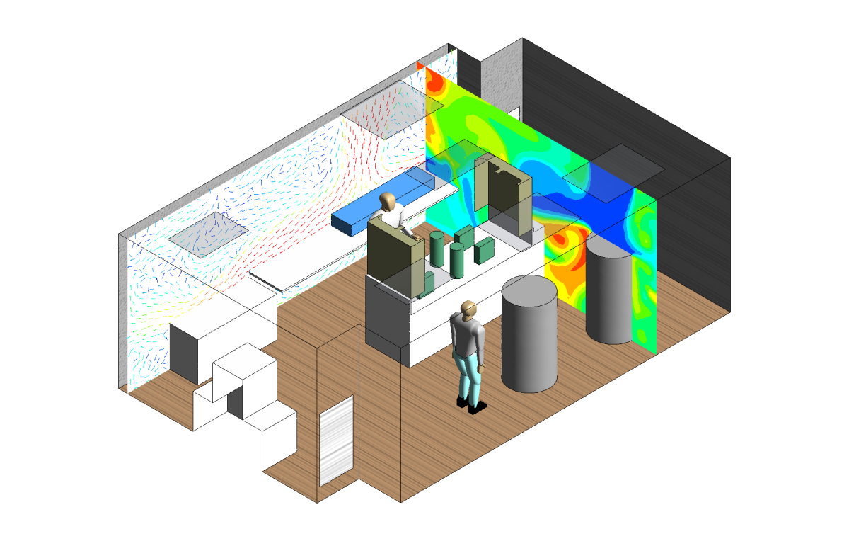
The aim of CFD simulation will be to characterize air circulation in the room, and to identify stagnation zones favorable to the accumulation of stale air, as well as overspeed and retro-contamination zones between work stations and operators, and to control maximum room temperature and humidity levels.


Optimisation du positionnement des diffuseurs pour une salle blanche

Simulation and results

To analyze the airflow in a cleanroom, OptiFluides carries out an aeraulic study using 3D software such as OpenFoam or ANSYS Fluent. To give you the best possible view of the air flow, we calculate :

  1. Air velocities,
  2. Residence times,
  3. Pressure field
  4. Temperature field,
  5. Hygrometry,
  6. The trajectory of pollutant particles potentially released into the room.

Local air recirculation zones, or zones where temperature, velocity or humidity are too high or too low, are highlighted. At the end of this initial modeling, we formulate any areas for improvement that we have identified.

Additional calculations can then be used to optimize the placement of exhaust and intake air, correct the temperature to improve thermal comfort, or modify the layout of the controlled-atmosphere zone.

Different approaches are available:

  1. Modeling a new configuration, with modifications based on initial results,
  2. Implementating an optimization method based on an objective function to be verified (e.g.: minimisation of residence time while verifying a maximum air velocity of 0.45 m/s and an air renewal rate of 30 vol/h).

The video below shows some examples of the results obtained using CFD simulation of a cleanroom:

Contact us

To find out more about CFD simulation of cleanrooms.